State diagrams describe the lifecycle of objects: possible states and transitions between them. They are ideal for documenting state machines, task status models, and business processes.
Basic Syntax
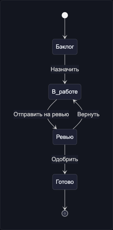
stateDiagram-v2
    [*] --> Backlog
    Backlog --> InProgress : Assign
    InProgress --> Review : Submit for review
    Review --> InProgress : Return
    Review --> Done : Approve
    Done --> [*]
[*] represents the initial or final state.
Nested States
stateDiagram-v2
    [*] --> InProgress

    state InProgress {
        [*] --> Development
        Development --> CodeReview : submit PR
        CodeReview --> Development : request changes
        CodeReview --> Testing : approved
        Testing --> Development : bug found
        Testing --> [*] : passed
    }

    InProgress --> Done : all checks passed
    Done --> [*]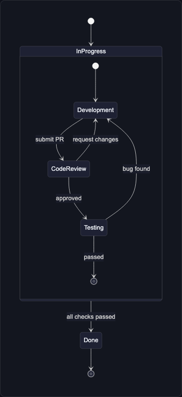
Parallel States
stateDiagram-v2
    [*] --> Deployment

    state Deployment {
        [*] --> Fork_state
        Fork_state --> Backend_Deploy
        Fork_state --> Frontend_Deploy
        Fork_state --> DB_Migration

        Backend_Deploy --> Join_state
        Frontend_Deploy --> Join_state
        DB_Migration --> Join_state

        Join_state --> [*]
    }

    Deployment --> [*]
Choice
stateDiagram-v2
[*] --> Validate
state if_valid <<choice>>
Validate --> if_valid
if_valid --> Approved : valid
if_valid --> Rejected : invalid
if_valid --> NeedsReview : partial
Approved --> [*]
Rejected --> [*]
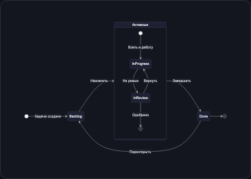
NeedsReview --> Validate : after changesExample: Task Lifecycle in FlowEra
stateDiagram-v2
    direction LR

    [*] --> Backlog : Task created

    state "Active" as Active {
        [*] --> InProgress : Start working
        InProgress --> InReview : Submit for review
        InReview --> InProgress : Return for changes
        InReview --> [*] : Approved
    }

    Backlog --> Active : Assign
    Active --> Done : Complete
    Done --> Backlog : Reopen

    state Done {
        [*] --> Verified
        Verified --> Released
    }

    Done --> [*]