ER diagrams (Entity-Relationship) describe the data structure: entities (tables), their attributes, and relationships. In FlowEra, they are used to document database schemas, API resources, and data structures.
Basic Syntax
erDiagram
    USER {
        uuid id PK
        string email UK
        string name
        timestamp created_at
    }

    TASK {
        uuid id PK
        uuid flow_id FK
        uuid assignee_id FK
        string title
        string status
        jsonb properties
    }

    FLOW {
        uuid id PK
        uuid tenant_id FK
        string name
        uuid status_model_id FK
    }

    USER ||--o{ TASK : "assigned to"
    FLOW ||--o{ TASK : "contains"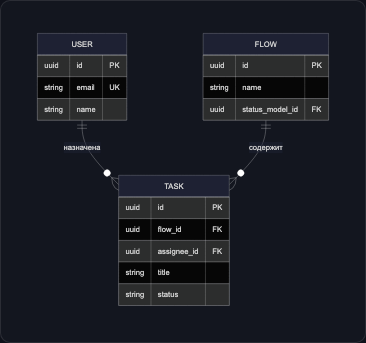
Relationship Types
| Symbol | Meaning |
|---|---|
|| | Exactly one |
|o | Zero or one |
}o | Zero or many |
}| | One or many |
erDiagram
DEPARTMENT ||--o{ EMPLOYEE : "works in"
EMPLOYEE }|--|| ADDRESS : "lives at"
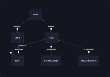
EMPLOYEE o|--o{ PROJECT : "works on"Example: FlowEra Schema
erDiagram
    TENANT {
        uuid id PK
        string name
        string slug UK
    }

    USER {
        uuid id PK
        uuid tenant_id FK
        string email UK
        string name
        string role
    }

    FLOW {
        uuid id PK
        uuid tenant_id FK
        uuid status_model_id FK
        string name
    }

    STATUS_MODEL {
        uuid id PK
        uuid tenant_id FK
        string name
        jsonb statuses
    }

    ITEM {
        uuid id PK
        uuid flow_id FK
        uuid assignee_id FK
        string title
        string status
        jsonb properties
    }

    TENANT ||--o{ USER : "has"
    TENANT ||--o{ FLOW : "owns"
    FLOW }o--|| STATUS_MODEL : "uses"
    FLOW ||--o{ ITEM : "contains"
    USER ||--o{ ITEM : "assigned"